

My first L297-298 stepper motor controller was made on prototyping board, which turned out to be a nightmare for two reasons:
Here are some pictures of my first board and, below those, a video of a stepper motor running off it:


http://www.youtube.com/watch?v=iRHaR10fej4
And here is the schematic (NOTE: this schematic is terrible, scroll down for a much better one):

A better way to make a stepper motor controller is to make a printed circuit board, and then simply drop the components in. After making the PCB, placing the components and soldering them hardly takes any time at all, in contrast to the proto board which took a ton of time to make. Here's a picture of the first stepper motor controller I made in PCB-form:

Here is the schematic for the PCB version of my stepper motor controller. Notice that some improvements were made, such as the Schmitt trigger to help filter out noise.
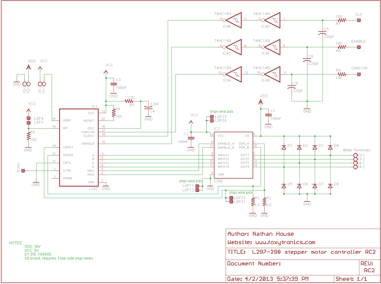
The Eagle Layout Editor schematic & PCB are available for download here: http://www.foxytroni...-schematic-rc2/
I want to thank Phil at PMinMO.com for his help when I was designing the PCB. He has a lot of experience with these stepper motor ICs and gave me a lot of advice. I also borrowed the idea of using a Schmitt trigger from him.
- It's really hard to keep track of all the wires and where they're supposed to go when you're trying to assemble the board.
- I meticulously cut all the wires to the "right" lengths and bent them at right angles because I wanted the stepper motor controller to look pretty (never again!).
Here are some pictures of my first board and, below those, a video of a stepper motor running off it:
http://www.youtube.com/watch?v=iRHaR10fej4
And here is the schematic (NOTE: this schematic is terrible, scroll down for a much better one):
A better way to make a stepper motor controller is to make a printed circuit board, and then simply drop the components in. After making the PCB, placing the components and soldering them hardly takes any time at all, in contrast to the proto board which took a ton of time to make. Here's a picture of the first stepper motor controller I made in PCB-form:
Here is the schematic for the PCB version of my stepper motor controller. Notice that some improvements were made, such as the Schmitt trigger to help filter out noise.
The Eagle Layout Editor schematic & PCB are available for download here: http://www.foxytroni...-schematic-rc2/
I want to thank Phil at PMinMO.com for his help when I was designing the PCB. He has a lot of experience with these stepper motor ICs and gave me a lot of advice. I also borrowed the idea of using a Schmitt trigger from him.


can you tell how to control clock signal????